

To read the original full thread and post questions/comments on this topic, please go to http://www.fjcruiserforums.com/foru...ums.com/forums/stereo-electronics/50761-ohms-law-fuses-american-wire-gauge.html
A little bit about fuses, ohm's law and the American Wire Gauge.
DISCLAIMER: This is serious business. This guide is no substitute for a careful and planned approach to working with electricity. You can easily be killed by less than 100 milli-amps, or 0.1 amps, should you become the electrical circuit. This guide is intended to be a layman's terms explanation of some of the confusing elements of electrical circuits. Please, please, please - be very careful.
Ohm's Law
"An electric circuit is formed when a conductive path is created to allow free electrons to continuously move. This continuous movement of free electrons through the conductors of a circuit is called a current, and it is often referred to in terms of "flow," just like the flow of a liquid through a hollow pipe.
The force motivating electrons to "flow" in a circuit is called voltage. Voltage is a specific measure of potential energy that is always relative between two points. When we speak of a certain amount of voltage being present in a circuit, we are referring to the measurement of how much potential energy exists to move electrons from one particular point in that circuit to another particular point. Without reference to two particular points, the term "voltage" has no meaning.
Free electrons tend to move through conductors with some degree of friction, or opposition to motion. This opposition to motion is more properly called resistance. The amount of current in a circuit depends on the amount of voltage available to motivate the electrons, and also the amount of resistance in the circuit to oppose electron flow. Just like voltage, resistance is a quantity relative between two points. For this reason, the quantities of voltage and resistance are often stated as being "between" or "across" two points in a circuit."
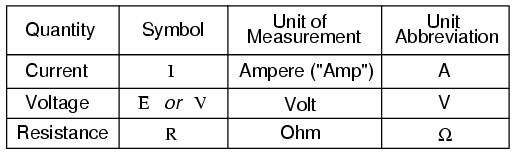
Ohm's Law Units:
![Image]()
The Relationship (this is the actual "Ohm's Law"):
This simple mathematical relationship is very powerful:
V=I*R
In Layman's Terms: Voltage is equal to current times resistance. We can also re-arrange the relationship to find other quantities. Likewise, current is equal to voltage divided by resistance and resistance is equal to the voltage divided by the current. In order to calculate any of this, you'll need two out of three values. Sometimes power (in watts) can also be helpful for calculating some of these values.
Power
"Power is the measure of how much work can be done in a given amount of time. Mechanical power is commonly measured (in America) in "horsepower. Electrical power is almost always measured in "watts."
Power's Relationship With Ohm's Law:
P=I*V
In Layman's Terms: Power is equal to current times the voltage. As above, we can use this equation to our advantage and re-arrange it to find whatever quantity we need.
Additional Note: Horsepower and watts are two different units for describing the same kind of physical measurement, where 1 horsepower equals 745.7 watts.
Make-It-All-Easy Stuff:
A very useful, but simple Ohm's Law online calculator to do things for you.
The Ultra-Useful Ohm's Law Unit Wheel (using E to represent V, obviously)
![Image]()
View attachment 21427
Fuses
"A fuse is a small, thin conductor designed to melt and separate into two pieces for the purpose of breaking a circuit in the event of excessive current. Fuses are primarily rated in terms of maximum current and fuses can be designed to blow fast, slow, or anywhere in between for the same maximum level of current. The best place to install a fuse in a grounded power system is on the ungrounded conductor path to the load. That way, when the fuse blows there will only be the grounded (safe) conductor still connected to the load, making it safer for people to be around."
For the following list, I either used 14.4 volts to calculate these estimations or directly referenced manufacturer data on the items. The 14.4 volts represents the maximum voltage that the alternator would put out if it was charging (a worst-case-scenario).
Some common accessories and recommended fuse values for them:
55 watt off-road lights (pair) = ~7.64A, use a 10A
100 watt off-road lights (pair) = ~13.9A, use a 15A
Back-up light(s) (stand-alone flood type, based on this with two 50W bulbs) = ~6.94A, use a 7.5A
Fog lights (based on this with two 55W bulbs) = ~7.64A, use a 10A
Driving lights (based on this with two 55W bulbs) = ~7.64A, use a 10A
5 watt CB radio (based on my Uniden PC78LTW) = ~1.2A, use a 2A
25 watt Ham radio = ?? (someone help me out here and give me a model to base this off of)
Satellite radio receiver (based on a Sirius Sportster 5) = ~1A, use a 2A
Flashlight charger (based on a Stinger XT) = ~0.7A, use a 1A or 2A
Switch to relay (based on measured maximum coil draw of a Bosch 40A relay) = ~0.3A, use a 1A or 2A
GPS unit (large, based on a Lowrance BAJA model) = ~2A, use a 3A
GPS unit (small) = ~1A, use a 2A
Spotlight (pillar mounted, 100W halogen bulb) = ~6.94A, use a 7.5A
Back-up camera system (based on a VR3 Backup Camera System) = use a 2A
100w siren/PA/horn system (based on this) = ~8.0A, use a 10A
Radar detector (based on an Escort Passport 8500 X50) = ~1A, use a 2A
Cell phone charger = ~1A, use a 2A
Dome light(s) (aftermarket) = ~2A, use a 5A
Stereo system power amps (based on an Alpine MRP-F300) = use a 50A
Sub-woofer (aftermarket, based on Alpine PLT-5) = use a 40A
12V AUX lighter socket = max. 10A, use a 10A
Cigarette lighter =
Some methods of approximating current draw:
Obviously the first and best method for approximating the current draw of an electronic item is to read the manual and look for the "specifications" or "operating requirements" section. This data is provided by the manufacturer and won't be wrong! The following method is really only to be used as a last resort. This method of approximating the current draw of a particular device is called terminal resistance measurement. For this, you take a DMM (digital multi-meter) and set it to your lowest resistance setting. Take your device which you'd like to check and make sure it's disconnected from the power source (both terminals, positive and negative). Connect one test lead to the positive wire of the device and the other lead to the negative wire of the device. The resistance reading is the internal resistance of the device's power supply circuitry. This is the resistance that the voltage source "sees" when the device is connected.
NOTE: The reason why this is an inaccurate measurement and in some cases, completely useless is that modern electronics are being designed with digital-based, SMPS (switch mode power supply) power supplies. These power supplies are constantly switching on and off the voltage to either raise or lower it to a particular level. This means that the power is coupled and de-coupled constantly, many times per second to keep a constant voltage level that the device it is powering needs. As I said before, these are the more common types of power supplies seen in modern, more efficient electronics. This means many of the devices in your car are most likely not able to be measured by this method. For methods of determining actual current draw, please continue.
Methods of actual current measurement:
The following methods are potentially very dangerous. The first method involves connecting one side of your digital multi-meter to the positive source of and connecting the device to the other side. The second method involves much higher and dangerous currents, being measured by a non-contact, inductive clamp meter.
A DMM photo for reference:
![Image]()
If your device is probably less than 10A, you'll want to measure it in series with the multi-meter.
Steps:
1) Make sure all power is disconnected.
2) Take your DMM and set it to measure the highest range of amperage (usually 10A on most hand-held DMM's).
3) Connect the test leads to your DMM appropriately. The red lead should go into the terminal marked "10A" and the black should go into the terminal marked "COM" (or similar, depending on your model - consult your user's manual).
4) Connect the red lead of your DMM to the positive voltage source.
5) Connect the black lead of your DMM to your device's positive voltage input.
6) Connect your device's negative input (or ground) to the negative output (or ground) on your voltage source.
7) Switch the power on and observe the current reading. This is the amount of current in Amps that your device is using while on.
An Inductive Clamp Meter photo for reference:
![Image]()
If your device is probably more than 10A, you're going to need to measure it with an inductive clamp meter.
These meters can measure the amount of current flowing through a wire due to the electromagnetic field that will build around the wire when current is flowing through it.
Steps:
1) Make sure all power is disconnected.
2) Take your device and hook up the positive input to your positive voltage source, as well as hook up your negative (or ground) input to the negative (or ground) on your voltage source.
3) Separate the wires so that the positive is not near the negative and the clamp meter can be placed around the positive wire.
4) Place the clamp meter around the positive wire ONLY. If you hook around both wires, you won't get any or an accurate measurement. It MUST be placed around the positive wire ONLY. Pay special attention to the arrow in the inside of the clamp, as this must be pointing towards the device (in the direction of the current flow, which is from the source to the device).
5) Power up the device and observe the reading. This is the amount of current in Amps that your device is using.
A note on wire selection and the American Wire Gauge:
One thing I suggest you follow properly is the Amperage ratings in the American Wire Gauge (AWG). You're going to want to note the Amps that your device is going to use and wire for it accordingly. For instance, if we have a device that's going to draw 13.2A, we'd use a 15A fuse and 14 Gauge wire to properly wire it. Sometimes when going longer distances you may be prone to "voltage drop" conditions where, due to the wire's resistance, the voltage may drop to an un-desirable level. This calculator may help with situations like that to select an appropriate wire gauge.
I hope this helps clear up some confusion about watts, amps, volts and ohms. If you've got any questions, comments, corrections, or can think of something I missed - please contact me. Oh and could someone please give me some data on a 25W HAM radio for the fuse recommendations section?
A little bit about fuses, ohm's law and the American Wire Gauge.
DISCLAIMER: This is serious business. This guide is no substitute for a careful and planned approach to working with electricity. You can easily be killed by less than 100 milli-amps, or 0.1 amps, should you become the electrical circuit. This guide is intended to be a layman's terms explanation of some of the confusing elements of electrical circuits. Please, please, please - be very careful.
Ohm's Law
"An electric circuit is formed when a conductive path is created to allow free electrons to continuously move. This continuous movement of free electrons through the conductors of a circuit is called a current, and it is often referred to in terms of "flow," just like the flow of a liquid through a hollow pipe.
The force motivating electrons to "flow" in a circuit is called voltage. Voltage is a specific measure of potential energy that is always relative between two points. When we speak of a certain amount of voltage being present in a circuit, we are referring to the measurement of how much potential energy exists to move electrons from one particular point in that circuit to another particular point. Without reference to two particular points, the term "voltage" has no meaning.
Free electrons tend to move through conductors with some degree of friction, or opposition to motion. This opposition to motion is more properly called resistance. The amount of current in a circuit depends on the amount of voltage available to motivate the electrons, and also the amount of resistance in the circuit to oppose electron flow. Just like voltage, resistance is a quantity relative between two points. For this reason, the quantities of voltage and resistance are often stated as being "between" or "across" two points in a circuit."
Ohm's Law Units:
The Relationship (this is the actual "Ohm's Law"):
This simple mathematical relationship is very powerful:
V=I*R
In Layman's Terms: Voltage is equal to current times resistance. We can also re-arrange the relationship to find other quantities. Likewise, current is equal to voltage divided by resistance and resistance is equal to the voltage divided by the current. In order to calculate any of this, you'll need two out of three values. Sometimes power (in watts) can also be helpful for calculating some of these values.
Power
"Power is the measure of how much work can be done in a given amount of time. Mechanical power is commonly measured (in America) in "horsepower. Electrical power is almost always measured in "watts."
Power's Relationship With Ohm's Law:
P=I*V
In Layman's Terms: Power is equal to current times the voltage. As above, we can use this equation to our advantage and re-arrange it to find whatever quantity we need.
Additional Note: Horsepower and watts are two different units for describing the same kind of physical measurement, where 1 horsepower equals 745.7 watts.
Make-It-All-Easy Stuff:
A very useful, but simple Ohm's Law online calculator to do things for you.
The Ultra-Useful Ohm's Law Unit Wheel (using E to represent V, obviously)
View attachment 21427
Fuses
"A fuse is a small, thin conductor designed to melt and separate into two pieces for the purpose of breaking a circuit in the event of excessive current. Fuses are primarily rated in terms of maximum current and fuses can be designed to blow fast, slow, or anywhere in between for the same maximum level of current. The best place to install a fuse in a grounded power system is on the ungrounded conductor path to the load. That way, when the fuse blows there will only be the grounded (safe) conductor still connected to the load, making it safer for people to be around."
For the following list, I either used 14.4 volts to calculate these estimations or directly referenced manufacturer data on the items. The 14.4 volts represents the maximum voltage that the alternator would put out if it was charging (a worst-case-scenario).
Some common accessories and recommended fuse values for them:
55 watt off-road lights (pair) = ~7.64A, use a 10A
100 watt off-road lights (pair) = ~13.9A, use a 15A
Back-up light(s) (stand-alone flood type, based on this with two 50W bulbs) = ~6.94A, use a 7.5A
Fog lights (based on this with two 55W bulbs) = ~7.64A, use a 10A
Driving lights (based on this with two 55W bulbs) = ~7.64A, use a 10A
5 watt CB radio (based on my Uniden PC78LTW) = ~1.2A, use a 2A
25 watt Ham radio = ?? (someone help me out here and give me a model to base this off of)
Satellite radio receiver (based on a Sirius Sportster 5) = ~1A, use a 2A
Flashlight charger (based on a Stinger XT) = ~0.7A, use a 1A or 2A
Switch to relay (based on measured maximum coil draw of a Bosch 40A relay) = ~0.3A, use a 1A or 2A
GPS unit (large, based on a Lowrance BAJA model) = ~2A, use a 3A
GPS unit (small) = ~1A, use a 2A
Spotlight (pillar mounted, 100W halogen bulb) = ~6.94A, use a 7.5A
Back-up camera system (based on a VR3 Backup Camera System) = use a 2A
100w siren/PA/horn system (based on this) = ~8.0A, use a 10A
Radar detector (based on an Escort Passport 8500 X50) = ~1A, use a 2A
Cell phone charger = ~1A, use a 2A
Dome light(s) (aftermarket) = ~2A, use a 5A
Stereo system power amps (based on an Alpine MRP-F300) = use a 50A
Sub-woofer (aftermarket, based on Alpine PLT-5) = use a 40A
12V AUX lighter socket = max. 10A, use a 10A
Cigarette lighter =
Some methods of approximating current draw:
Obviously the first and best method for approximating the current draw of an electronic item is to read the manual and look for the "specifications" or "operating requirements" section. This data is provided by the manufacturer and won't be wrong! The following method is really only to be used as a last resort. This method of approximating the current draw of a particular device is called terminal resistance measurement. For this, you take a DMM (digital multi-meter) and set it to your lowest resistance setting. Take your device which you'd like to check and make sure it's disconnected from the power source (both terminals, positive and negative). Connect one test lead to the positive wire of the device and the other lead to the negative wire of the device. The resistance reading is the internal resistance of the device's power supply circuitry. This is the resistance that the voltage source "sees" when the device is connected.
NOTE: The reason why this is an inaccurate measurement and in some cases, completely useless is that modern electronics are being designed with digital-based, SMPS (switch mode power supply) power supplies. These power supplies are constantly switching on and off the voltage to either raise or lower it to a particular level. This means that the power is coupled and de-coupled constantly, many times per second to keep a constant voltage level that the device it is powering needs. As I said before, these are the more common types of power supplies seen in modern, more efficient electronics. This means many of the devices in your car are most likely not able to be measured by this method. For methods of determining actual current draw, please continue.
Methods of actual current measurement:
The following methods are potentially very dangerous. The first method involves connecting one side of your digital multi-meter to the positive source of and connecting the device to the other side. The second method involves much higher and dangerous currents, being measured by a non-contact, inductive clamp meter.
A DMM photo for reference:

If your device is probably less than 10A, you'll want to measure it in series with the multi-meter.
Steps:
1) Make sure all power is disconnected.
2) Take your DMM and set it to measure the highest range of amperage (usually 10A on most hand-held DMM's).
3) Connect the test leads to your DMM appropriately. The red lead should go into the terminal marked "10A" and the black should go into the terminal marked "COM" (or similar, depending on your model - consult your user's manual).
4) Connect the red lead of your DMM to the positive voltage source.
5) Connect the black lead of your DMM to your device's positive voltage input.
6) Connect your device's negative input (or ground) to the negative output (or ground) on your voltage source.
7) Switch the power on and observe the current reading. This is the amount of current in Amps that your device is using while on.
An Inductive Clamp Meter photo for reference:

If your device is probably more than 10A, you're going to need to measure it with an inductive clamp meter.
These meters can measure the amount of current flowing through a wire due to the electromagnetic field that will build around the wire when current is flowing through it.
Steps:
1) Make sure all power is disconnected.
2) Take your device and hook up the positive input to your positive voltage source, as well as hook up your negative (or ground) input to the negative (or ground) on your voltage source.
3) Separate the wires so that the positive is not near the negative and the clamp meter can be placed around the positive wire.
4) Place the clamp meter around the positive wire ONLY. If you hook around both wires, you won't get any or an accurate measurement. It MUST be placed around the positive wire ONLY. Pay special attention to the arrow in the inside of the clamp, as this must be pointing towards the device (in the direction of the current flow, which is from the source to the device).
5) Power up the device and observe the reading. This is the amount of current in Amps that your device is using.
A note on wire selection and the American Wire Gauge:
One thing I suggest you follow properly is the Amperage ratings in the American Wire Gauge (AWG). You're going to want to note the Amps that your device is going to use and wire for it accordingly. For instance, if we have a device that's going to draw 13.2A, we'd use a 15A fuse and 14 Gauge wire to properly wire it. Sometimes when going longer distances you may be prone to "voltage drop" conditions where, due to the wire's resistance, the voltage may drop to an un-desirable level. This calculator may help with situations like that to select an appropriate wire gauge.
I hope this helps clear up some confusion about watts, amps, volts and ohms. If you've got any questions, comments, corrections, or can think of something I missed - please contact me. Oh and could someone please give me some data on a 25W HAM radio for the fuse recommendations section?


