2011 Audio Mod - Part 1 of 7
Part 1 of 7
Part 1: Goal, budget, and component selection
I have completed my upgrade to my 2011 FJ's sound system, and I am happy with the results.
My goal was to retain the stock single CD head end unit, not add a subwoofer(s), and not add an amplifier. (Edit: I changed my mind later and added a modded factory sub and a small amp under the driver's seat to power it.)
The sound quality is very good in my opinion, and I only spent about $125 on speakers, $100 on undercoating, and $75 on Dynamat. It isn't Earth-shaking sound, but is is good, clean sound with enough solid and punchy bass for most people as well as very nice midrange and treble too.
I started with the basic 2011 FJ 6 speaker sound system, which consists of:
Single disc in-dash head end unit
Steering wheel audio and bluetooth controls
One pair of 2 inch "sort-of" tweeters in the dashboard
One pair of dual cone plastic frame (yes, plastic) 6x9's in the front doors
One pair of vibrating "exciters" making unbelievably bad sound by vibrating the headliner
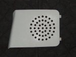
Ouch. Look at the attached pics of the factory 6x9's. What on Earth is Toyota doing? It's a paper dual cone speaker with a fabric surround glued onto a plastic frame! I have never seen anything like it. The magnet is about the size of a quarter.
The construction of the 2" dashboard tweeters isn't so horrible, and Toyota even put crossover capacitors on them. They don't sound so good though.
The vibrating headliner "exciters" are garbage in my opinion. Since I have no speakers in the rear pillars, I can fade all the way to the rear and hear only these headliner vibrators. They are awful.
I cut and capped the wires in the A pillar to kill the "exciting" headliner vibrators (junk). Be aware that in the 2011 one red wire in the A pillar powers the +12 volt for the map and dome lights while the other (twisted in a pair) is the vibrating exciter piece of junk. When in doubt, nick the insulation and test for +12 volts. If +12 volt is there, you can carefully tape up the nick with professional quality electical tape and you have not cut the wrong wire. Update: On the 2011 basic six speaker system, you can simply unplug them from the back of the in-dash unit.
New speakers:
Rockford Fosgate Punch P1692 6x9 coaxials - $64.99 per pair - front doors
Rockford Fosgate Punch P132 3-1/2 coaxials - $39.99 per pair - in dash
Why did I choose these speakers? Short answer: they are very well built and well engineered at a very good price. Long answer (read on): that means they have things like durable rubber surrounds, heavy frames, rubber anti-rust protectors around the magnets, decent efficiency that is not overstated by super bright tweeters driving up the sensitivity rating, and the attention to detail to run the tweeter wires around the magnet and through the center pole piece rather than piercing the 6x9 cone to get power to the tweeters. I also knew that not only was this wire routing good engineering, but that it would allow me to cut the tweeter wires easily if I wanted to (and I did), leaving me with what pretty much is just a 6x9 mid-bass driver. Also significant in my choice it that the tweeter is reasonably small and will have little effect just from being physically present. Compare that to some 6x9's where there is a 2 inch "mid" and maybe one or two more "super tweeters" in the center almost completely obstructing the 6x9. That's not just physics, it's a no-brainer. All of these advantages and benefits come at a very reasonable price with the Rockfords.
I also knew from previous experience (and a little physics) that they would not be overly bright. They definitely do not lack highs, but they are not bright. With an interior as reflective as the rubber and plastic FJ, you don't want screaming highs bouncing all over the place.
I knew the Rockford 3 1/2's would match the Rockford 6x9's in timbre due to their almost identical construction. Timbre matching is important. I also knew I could engineer the crossovers and attenuation properly while still maintaining a suitable impedence (above 4 ohms total).
-FJ Florida-
Part 1 of 7
Part 1: Goal, budget, and component selection
I have completed my upgrade to my 2011 FJ's sound system, and I am happy with the results.
My goal was to retain the stock single CD head end unit, not add a subwoofer(s), and not add an amplifier. (Edit: I changed my mind later and added a modded factory sub and a small amp under the driver's seat to power it.)
The sound quality is very good in my opinion, and I only spent about $125 on speakers, $100 on undercoating, and $75 on Dynamat. It isn't Earth-shaking sound, but is is good, clean sound with enough solid and punchy bass for most people as well as very nice midrange and treble too.
I started with the basic 2011 FJ 6 speaker sound system, which consists of:
Single disc in-dash head end unit
Steering wheel audio and bluetooth controls
One pair of 2 inch "sort-of" tweeters in the dashboard
One pair of dual cone plastic frame (yes, plastic) 6x9's in the front doors
One pair of vibrating "exciters" making unbelievably bad sound by vibrating the headliner
Ouch. Look at the attached pics of the factory 6x9's. What on Earth is Toyota doing? It's a paper dual cone speaker with a fabric surround glued onto a plastic frame! I have never seen anything like it. The magnet is about the size of a quarter.
The construction of the 2" dashboard tweeters isn't so horrible, and Toyota even put crossover capacitors on them. They don't sound so good though.
The vibrating headliner "exciters" are garbage in my opinion. Since I have no speakers in the rear pillars, I can fade all the way to the rear and hear only these headliner vibrators. They are awful.
I cut and capped the wires in the A pillar to kill the "exciting" headliner vibrators (junk). Be aware that in the 2011 one red wire in the A pillar powers the +12 volt for the map and dome lights while the other (twisted in a pair) is the vibrating exciter piece of junk. When in doubt, nick the insulation and test for +12 volts. If +12 volt is there, you can carefully tape up the nick with professional quality electical tape and you have not cut the wrong wire. Update: On the 2011 basic six speaker system, you can simply unplug them from the back of the in-dash unit.
New speakers:
Rockford Fosgate Punch P1692 6x9 coaxials - $64.99 per pair - front doors
Rockford Fosgate Punch P132 3-1/2 coaxials - $39.99 per pair - in dash
Why did I choose these speakers? Short answer: they are very well built and well engineered at a very good price. Long answer (read on): that means they have things like durable rubber surrounds, heavy frames, rubber anti-rust protectors around the magnets, decent efficiency that is not overstated by super bright tweeters driving up the sensitivity rating, and the attention to detail to run the tweeter wires around the magnet and through the center pole piece rather than piercing the 6x9 cone to get power to the tweeters. I also knew that not only was this wire routing good engineering, but that it would allow me to cut the tweeter wires easily if I wanted to (and I did), leaving me with what pretty much is just a 6x9 mid-bass driver. Also significant in my choice it that the tweeter is reasonably small and will have little effect just from being physically present. Compare that to some 6x9's where there is a 2 inch "mid" and maybe one or two more "super tweeters" in the center almost completely obstructing the 6x9. That's not just physics, it's a no-brainer. All of these advantages and benefits come at a very reasonable price with the Rockfords.
I also knew from previous experience (and a little physics) that they would not be overly bright. They definitely do not lack highs, but they are not bright. With an interior as reflective as the rubber and plastic FJ, you don't want screaming highs bouncing all over the place.
I knew the Rockford 3 1/2's would match the Rockford 6x9's in timbre due to their almost identical construction. Timbre matching is important. I also knew I could engineer the crossovers and attenuation properly while still maintaining a suitable impedence (above 4 ohms total).
-FJ Florida-
")