The most vulnerable part of the drive mechanics in an IFS 4x4 is the front CV axle. This has been true through several generations of IFS 4x4's. This part, specifically the CV joint, is the most common major mechanical failure that I know of when people push their IFS rigs, rock crawling on challenging trails. I have little or no experience in muddy types of 4-wheeling, but I can't imagine it's much different.
Several popular upgrades contribute to putting this part at risk. The most common is large tires. Larger tires put a proportionally larger torsional load on the axle. Another is gearing modifications. Lower gears, increasing "crawl ratio", also increase the torque multiplication by the same amount. Finally, suspension modifications which facilitate the creation of situations where the CV joint is maximally articulated (to the extreme of it's capacity for misalignment) also facilitate putting this joint into it's weakest orientation, relative to torsional loading.
If you put on big tires and big gears, and you turn the steering wheel to full lock, and you gas it against an obstacle, you'll snap the CV joint.
I know.")
The question is, "What are you going to do about it?"
My contingency plan for a broken CV axle has been to utilize my front air locker and maintain 3-wheel drive after the failure... then roll home in 2WD after the trail with the broken axle clacking... and THEN deal with it.
Saturday evening, I drove home from the All-Pro Claw Hammer event, to Phoenix, AZ (almost 300 miles) with a clacking CV axle.
I'm no longer in love with this plan!
The question arises as to whether or not this would be a do-able trail repair. My answer to that is a guarded, "yes... but..."
Don't expect to do it in an hour.
Don't expect to do it the first time on the trail.
Don't expect to do it unless you're ready with a complete kit of parts and tools dedicated to this specific repair!
This post is the DISTILLATION of my experience changing out a broken CV axle in ideal conditions in my driveway.
If you read this, and you have some mechanical capability, and you have the right tools, you can do this repair. It took me most of the day to figure this out, including hunting online for some info, and making 3 runs to Checkers Auto Parts, although I had a couple other things going on, helping out around the house.
Having done this once, I think I could do it on a trail as long as the conditions were optimized and I came prepared. It would take 2 or 3 hours. "Optimized conditions" means getting the FJC out of the rocks and onto relatively flat solid ground, hopefully out of the beating sun.
The procedure below is the STREAMLINED version of what I had to figure out as I went. If you can streamline the process any further, please share! I'll benefit from your help. I'm likely to have to do this again in the future!!!
CHANGING A CV AXLE:
I recommend the following list of tools, supplies and parts:
1/2" drive socket wrench and metric socket set
1/2" drive air impact wrench
If you don't have an impact wrench, get a 2 or 3 foot piece of STRONG steel tube that can go over the handle of your ratchet - to make a "cheater bar"... and have a back up socket wrench ratchet in case you snap your tool with the cheater bar (if you do, it serves you right for buying crap tools).
Sockets used:
12mm
14mm
17mm
19mm
35mm (for the spindle nut)
10mm allen-head type socket wrench attachment
-whatever socket for the wheel lug nuts (13/16" for my Gorilla lug nuts)
... and find your locking lug socket!
17mm open ended/box end wrench
Pliers
Slide Hammer with hook attachment.
4.25" hose clamp (and standard screw driver to tighten it)
1 jack stand (or if you're in the field - use the Hi-Lift and pray for safety)
1 floor jack (or if you're in the field, use the bottle jack and a good rock)
- you need to use the floor/bottle jack WHILE the vehicle is jacked, meaning you need *BOTH*
Catch basin for oil (and a seal-able empty 2 liter container to carry it away in, if you're in the field - and if so, then you also need a funnel)
Grease (for seals - not a lot)
Gear oil (have 2 quarts on hand - you use about 1 and a half).
Gear oil hose attachment
Brake cleaner
Paper towels (shop type)
Plastic trash bags
Unless you want to drive home wiping grease on your steering wheel and everything else you touch...
Hand cleaner
Baby wipes (these work awesome... works well on gunpowder residue also)
? rubber gloves (if you think you can avoid getting dirty by using them)
This is likely to be an epic saga... so consider:
Lantern style flashlight(s)
warm clothes
plastic tarp
For after you finish:
either a crisis intervention psychologist...
.. or a beer.
PROCEDURE:
1) Unbolt and drop any front end armor that goes under the front differential. (12 or 14mm socket - depending on your style of bolts). If you're suicidal enough to do this repair depending on your Hi-Lift for support, then be SURE to drop the armor plate FIRST, so that you don't have to crawl under the Hi-Lift supported vehicle.
2) Locate the drain plug on the differential, low on the driver's side. Position a catch basin beneath and remove the drain plug to empty out all the oil (10mm allen wrench or allen headed socket wrench attachment). As above, do this before using the Hi-Lift, if you have to go that route.
3) Break the lug nuts free. Jack up the side of the front end with the broken axle and support it with the jack stand (or the Hi-Lift and a prayer) so that the wheel is off the ground. Remove the wheel.
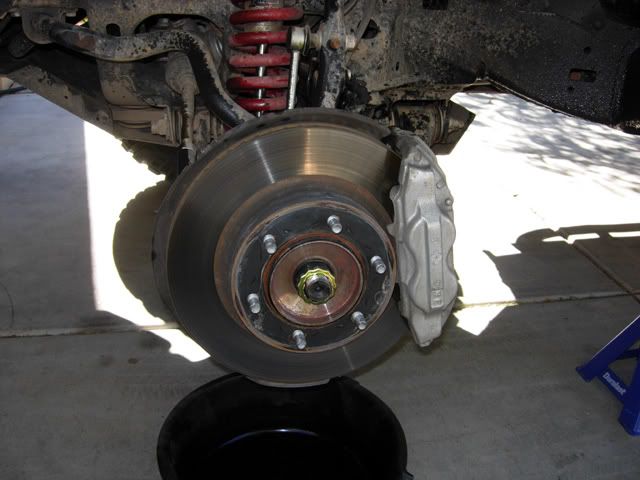
4) Pry the center cap off of the hub.
It should look like this:
![Image]()
5) Remove the brake caliper. There are 2 bolts holding it on in the back (17 mm socket). They're torqued nice and tight. Crank hard to get them loose.
6) Remove the bracket on the side of the spindle arm which contains the brake hose fitting so that you can swing the brakes way out of the work field (12 mm socket).
7) Unplug the electrical connector at the wheel sensor. The electrical connector is on the inside/front of the knuckle, if you look around behind the dust cover that backs the brake rotor. To unseat it, slide a standard screwdriver inside it and it comes free with no resistance. If you meet resistance, you haven't got the right spot. Once the electric wire is free, the brake caliper can be swung way off to the side. I suggest tying it up to the frame rail with scrap wire or string, to take the weight off the hose.
8) Support the lower control arm with a floor jack (or bottle jack) and crank up a little bit. Unbolt the sway bar link from the spindle arm.
6) Now the brake rotor lifts right off. It's not independently attached!
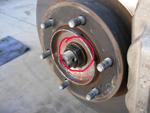
7) Straighten and remove the cotter pin that keeps the spindle nut retainer in place, and remove the spindle nut retainer (gold colored zinc plated thingy).
You should have something that looks like this:
![Image]()
8) Wrench off the spindle nut with the impact wrench or cheater bar. Some people say not to use the impact wrench. I say not to get a hernia (or if you do... call me...)
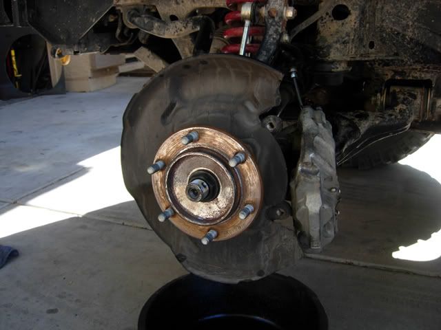
9) Using a 17mm open wrench, unfasten the 4 bolts that hold the spindle and hub onto the knuckle. This section can be removed as a unit complete with bearing. It has an O-ring around it. KEEP THIS PART CLEAN!! Once this is free, the brake rotor dust cover falls off.
Here, you can see how the spindle bolts are captured in this assembly if you remove it as a unit instead of trying to dismantle it:
![Image]()
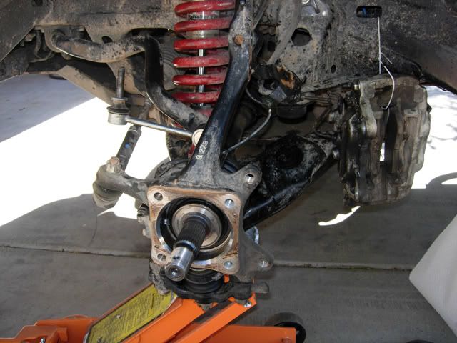
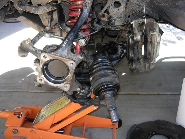
Here is what the knuckle mechanism looks like with everything removed. It's ready to swing out of the way in order to release the CV axle.
![Image]()
Is it possible to do this without removing the spindle and dust cover? I suspect that with the broken CV joint, you actually COULD remove the knuckle off of the axle outer, but I'm not sure if you could get the new one in without taking advantage of the extra "articulation" you get out of a crunched CV joint... I just don't know! For now, how I'm describing this is my exact plan for how to do it again next time.
10) Next, MAKE SURE THE LOWER CONTROL ARM IS SUPPORTED BY A JACK and unfasten the two bolts that go up through the ball joint bracket on the bottom of the knuckle. (19mm socket) This is facilitated by an air impact wrench or a cheater bar (or just risk the hernia).
11) Let the lower control arm drop away from the knuckle. Now, the knuckle can be unattached and rotated away from the CV axle.
It should look like this:
![Image]()
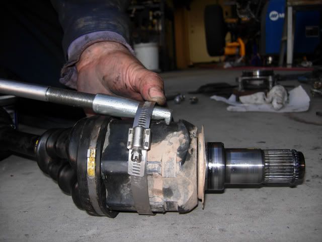
12) Now it's time to yank the axle assembly out of the differential housing. The inner shaft has a snap-in C clip on the end that plugs into the housing. It snaps right back out, but the correct force needs to be applied! This part took me the longest to figure out. The correct move requires the right tool!
Assemble a SLIDE HAMMER with the "hook attachment". The housing of the TULIP JOINT is what you see sticking out away from the differential housing. The tulip joint has machined notches for you to get ahold of with the slide hammer. The trouble is that they're designed for the specialty slide-hammer attachment for this job which is a Toyota proprietary part. With a regular old slide hammer, the hook attachment slips right off with every blow!
My solution was to anchor the hook in place inside of it's notch using a hose clamp. I wrapped the hose clamp around the tulip joint and around the slide hammer's hook, and then tightened it down. Here is the basic concept of the arrangement, being demonstrated on the axle after it was removed. Note the snap C ring inset into the end of the inner shaft:
![Image]()
Once the hook is secured to the axle, severeal solid raps with the slide hammer are enough to pop it free.
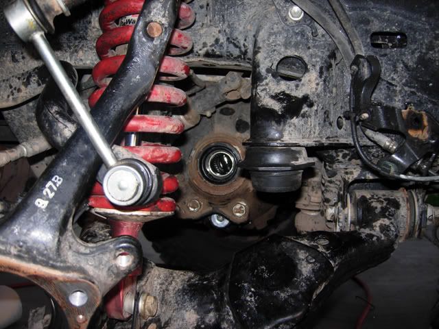
Here's what the hole looks like where the axle used to be:
![Image]()
13) Make sure the seals are CLEAN. There should be one inside the knuckle and one inside the differential housing.
Make sure the sealing SURFACES on the axle shafts are clean (use brake cleaner on the metal).
Grease the seals.
14) Plug the replacement axle into the differential housing. It's going to take a little UMPH to get it in there. If you've got the vehicle standing on a Hi-Lift, then WATCH OUT that you don't push it off!
15) Plug the drain hole in the differential securely and open the fill port above (and slightly rear-ward) with the 10 mm allen-head wrench (or socket attachment). Position the oil catch basin under the differential, and use the filler hose attachment on the gear oil bottles. Fill the differential housing till gear oil backflows out the fill hole, then cap it off securely with the plug.
16) Reassemble parts in reverse. Use the jack to close up the lower control arm to the knuckle and bolt it together. Replace the dust cover, and then the spindle and hub. Reapply the spindle nut and get it TIGHT and then back it up with the retainer and cotter pin. Replace the brake rotor and caliper, plug the sensor wire back in, and bolt the brake line back onto the spindle arm. Put the sway bar link back on (go up or down with the jack under the lower control arm, in order to make it stab in freely). Replace the center cap, the wheel and your lug nuts.
I benefitted from my front locking differential when I put the spindle nut back on. I started tightening the nut, and I just spun the axle instead. I powered up the compressor and locked the differential, but then it still spun because I was rotating the driveshaft. Finally, I put it in 4WD, and stabilized the driveshaft. If you don't have a front locker, then make sure you START this process while 4WD is engaged (so that the ADD is engaged). I'm not sure if the ADD stays engaged when the power is off, so if you don't have a locker, you should probably figure this out first! Otherwise, you're going to have to do something esle to figure out how to get the axle to stop spinning while you're tightening the nut.
Good luck.
*Edit: brought up from a later post*
ADDENDUM:
Key Torque Specs
If you want to do this right, have a torque wrench on hand... a big one.
Bolts on the bottom of the knuckle, next to the ball joint on the lower control arm: 118 ft. lbs.
Bolts that hold the brake caliper on the knuckle: 91 ft. lbs.
Sway bar link nut: 52 ft. lbs.
SPINDLE NUT: 174 ft. lbs.
Several popular upgrades contribute to putting this part at risk. The most common is large tires. Larger tires put a proportionally larger torsional load on the axle. Another is gearing modifications. Lower gears, increasing "crawl ratio", also increase the torque multiplication by the same amount. Finally, suspension modifications which facilitate the creation of situations where the CV joint is maximally articulated (to the extreme of it's capacity for misalignment) also facilitate putting this joint into it's weakest orientation, relative to torsional loading.
If you put on big tires and big gears, and you turn the steering wheel to full lock, and you gas it against an obstacle, you'll snap the CV joint.
I know.
The question is, "What are you going to do about it?"
My contingency plan for a broken CV axle has been to utilize my front air locker and maintain 3-wheel drive after the failure... then roll home in 2WD after the trail with the broken axle clacking... and THEN deal with it.
Saturday evening, I drove home from the All-Pro Claw Hammer event, to Phoenix, AZ (almost 300 miles) with a clacking CV axle.
I'm no longer in love with this plan!
The question arises as to whether or not this would be a do-able trail repair. My answer to that is a guarded, "yes... but..."
Don't expect to do it in an hour.
Don't expect to do it the first time on the trail.
Don't expect to do it unless you're ready with a complete kit of parts and tools dedicated to this specific repair!
This post is the DISTILLATION of my experience changing out a broken CV axle in ideal conditions in my driveway.
If you read this, and you have some mechanical capability, and you have the right tools, you can do this repair. It took me most of the day to figure this out, including hunting online for some info, and making 3 runs to Checkers Auto Parts, although I had a couple other things going on, helping out around the house.
Having done this once, I think I could do it on a trail as long as the conditions were optimized and I came prepared. It would take 2 or 3 hours. "Optimized conditions" means getting the FJC out of the rocks and onto relatively flat solid ground, hopefully out of the beating sun.
The procedure below is the STREAMLINED version of what I had to figure out as I went. If you can streamline the process any further, please share! I'll benefit from your help. I'm likely to have to do this again in the future!!!
CHANGING A CV AXLE:
I recommend the following list of tools, supplies and parts:
1/2" drive socket wrench and metric socket set
1/2" drive air impact wrench
If you don't have an impact wrench, get a 2 or 3 foot piece of STRONG steel tube that can go over the handle of your ratchet - to make a "cheater bar"... and have a back up socket wrench ratchet in case you snap your tool with the cheater bar (if you do, it serves you right for buying crap tools).
Sockets used:
12mm
14mm
17mm
19mm
35mm (for the spindle nut)
10mm allen-head type socket wrench attachment
-whatever socket for the wheel lug nuts (13/16" for my Gorilla lug nuts)
... and find your locking lug socket!
17mm open ended/box end wrench
Pliers
Slide Hammer with hook attachment.
4.25" hose clamp (and standard screw driver to tighten it)
1 jack stand (or if you're in the field - use the Hi-Lift and pray for safety)
1 floor jack (or if you're in the field, use the bottle jack and a good rock)
- you need to use the floor/bottle jack WHILE the vehicle is jacked, meaning you need *BOTH*
Catch basin for oil (and a seal-able empty 2 liter container to carry it away in, if you're in the field - and if so, then you also need a funnel)
Grease (for seals - not a lot)
Gear oil (have 2 quarts on hand - you use about 1 and a half).
Gear oil hose attachment
Brake cleaner
Paper towels (shop type)
Plastic trash bags
Unless you want to drive home wiping grease on your steering wheel and everything else you touch...
Hand cleaner
Baby wipes (these work awesome... works well on gunpowder residue also)
? rubber gloves (if you think you can avoid getting dirty by using them)
This is likely to be an epic saga... so consider:
Lantern style flashlight(s)
warm clothes
plastic tarp
For after you finish:
either a crisis intervention psychologist...
.. or a beer.
PROCEDURE:
1) Unbolt and drop any front end armor that goes under the front differential. (12 or 14mm socket - depending on your style of bolts). If you're suicidal enough to do this repair depending on your Hi-Lift for support, then be SURE to drop the armor plate FIRST, so that you don't have to crawl under the Hi-Lift supported vehicle.
2) Locate the drain plug on the differential, low on the driver's side. Position a catch basin beneath and remove the drain plug to empty out all the oil (10mm allen wrench or allen headed socket wrench attachment). As above, do this before using the Hi-Lift, if you have to go that route.
3) Break the lug nuts free. Jack up the side of the front end with the broken axle and support it with the jack stand (or the Hi-Lift and a prayer) so that the wheel is off the ground. Remove the wheel.
4) Pry the center cap off of the hub.
It should look like this:
5) Remove the brake caliper. There are 2 bolts holding it on in the back (17 mm socket). They're torqued nice and tight. Crank hard to get them loose.
6) Remove the bracket on the side of the spindle arm which contains the brake hose fitting so that you can swing the brakes way out of the work field (12 mm socket).
7) Unplug the electrical connector at the wheel sensor. The electrical connector is on the inside/front of the knuckle, if you look around behind the dust cover that backs the brake rotor. To unseat it, slide a standard screwdriver inside it and it comes free with no resistance. If you meet resistance, you haven't got the right spot. Once the electric wire is free, the brake caliper can be swung way off to the side. I suggest tying it up to the frame rail with scrap wire or string, to take the weight off the hose.
8) Support the lower control arm with a floor jack (or bottle jack) and crank up a little bit. Unbolt the sway bar link from the spindle arm.
6) Now the brake rotor lifts right off. It's not independently attached!
7) Straighten and remove the cotter pin that keeps the spindle nut retainer in place, and remove the spindle nut retainer (gold colored zinc plated thingy).
You should have something that looks like this:
8) Wrench off the spindle nut with the impact wrench or cheater bar. Some people say not to use the impact wrench. I say not to get a hernia (or if you do... call me...)
9) Using a 17mm open wrench, unfasten the 4 bolts that hold the spindle and hub onto the knuckle. This section can be removed as a unit complete with bearing. It has an O-ring around it. KEEP THIS PART CLEAN!! Once this is free, the brake rotor dust cover falls off.
Here, you can see how the spindle bolts are captured in this assembly if you remove it as a unit instead of trying to dismantle it:

Here is what the knuckle mechanism looks like with everything removed. It's ready to swing out of the way in order to release the CV axle.
Is it possible to do this without removing the spindle and dust cover? I suspect that with the broken CV joint, you actually COULD remove the knuckle off of the axle outer, but I'm not sure if you could get the new one in without taking advantage of the extra "articulation" you get out of a crunched CV joint... I just don't know! For now, how I'm describing this is my exact plan for how to do it again next time.
10) Next, MAKE SURE THE LOWER CONTROL ARM IS SUPPORTED BY A JACK and unfasten the two bolts that go up through the ball joint bracket on the bottom of the knuckle. (19mm socket) This is facilitated by an air impact wrench or a cheater bar (or just risk the hernia).
11) Let the lower control arm drop away from the knuckle. Now, the knuckle can be unattached and rotated away from the CV axle.
It should look like this:
12) Now it's time to yank the axle assembly out of the differential housing. The inner shaft has a snap-in C clip on the end that plugs into the housing. It snaps right back out, but the correct force needs to be applied! This part took me the longest to figure out. The correct move requires the right tool!
Assemble a SLIDE HAMMER with the "hook attachment". The housing of the TULIP JOINT is what you see sticking out away from the differential housing. The tulip joint has machined notches for you to get ahold of with the slide hammer. The trouble is that they're designed for the specialty slide-hammer attachment for this job which is a Toyota proprietary part. With a regular old slide hammer, the hook attachment slips right off with every blow!
My solution was to anchor the hook in place inside of it's notch using a hose clamp. I wrapped the hose clamp around the tulip joint and around the slide hammer's hook, and then tightened it down. Here is the basic concept of the arrangement, being demonstrated on the axle after it was removed. Note the snap C ring inset into the end of the inner shaft:
Once the hook is secured to the axle, severeal solid raps with the slide hammer are enough to pop it free.
Here's what the hole looks like where the axle used to be:
13) Make sure the seals are CLEAN. There should be one inside the knuckle and one inside the differential housing.
Make sure the sealing SURFACES on the axle shafts are clean (use brake cleaner on the metal).
Grease the seals.
14) Plug the replacement axle into the differential housing. It's going to take a little UMPH to get it in there. If you've got the vehicle standing on a Hi-Lift, then WATCH OUT that you don't push it off!
15) Plug the drain hole in the differential securely and open the fill port above (and slightly rear-ward) with the 10 mm allen-head wrench (or socket attachment). Position the oil catch basin under the differential, and use the filler hose attachment on the gear oil bottles. Fill the differential housing till gear oil backflows out the fill hole, then cap it off securely with the plug.
16) Reassemble parts in reverse. Use the jack to close up the lower control arm to the knuckle and bolt it together. Replace the dust cover, and then the spindle and hub. Reapply the spindle nut and get it TIGHT and then back it up with the retainer and cotter pin. Replace the brake rotor and caliper, plug the sensor wire back in, and bolt the brake line back onto the spindle arm. Put the sway bar link back on (go up or down with the jack under the lower control arm, in order to make it stab in freely). Replace the center cap, the wheel and your lug nuts.
I benefitted from my front locking differential when I put the spindle nut back on. I started tightening the nut, and I just spun the axle instead. I powered up the compressor and locked the differential, but then it still spun because I was rotating the driveshaft. Finally, I put it in 4WD, and stabilized the driveshaft. If you don't have a front locker, then make sure you START this process while 4WD is engaged (so that the ADD is engaged). I'm not sure if the ADD stays engaged when the power is off, so if you don't have a locker, you should probably figure this out first! Otherwise, you're going to have to do something esle to figure out how to get the axle to stop spinning while you're tightening the nut.
Good luck.
*Edit: brought up from a later post*
ADDENDUM:
Key Torque Specs
If you want to do this right, have a torque wrench on hand... a big one.
Bolts on the bottom of the knuckle, next to the ball joint on the lower control arm: 118 ft. lbs.
Bolts that hold the brake caliper on the knuckle: 91 ft. lbs.
Sway bar link nut: 52 ft. lbs.
SPINDLE NUT: 174 ft. lbs.